

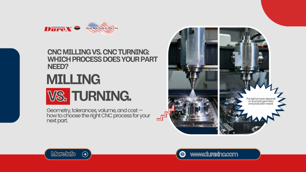
CNC milling uses a rotating cutting tool to machine a fixed workpiece, making it the better fit for complex, flat, pocketed, or irregular parts. CNC turning rotates the workpiece against a stationary cutting tool, which makes it the stronger choice for shafts, bushings, fittings, and other components built around a central axis.
Both are subtractive CNC processes, but the real difference comes down to which element does the rotating — the tool or the part itself. The right process for your job depends on the part’s geometry, feature orientation, tolerances, production volume, and downstream finishing needs — a decision most engineers frame simply as CNC Milling vs CNC Turning.
What is CNC Milling?
CNC milling is a machining process in which a rotating cutting tool removes material from a stationary or indexed workpiece to create a finished part. Unlike turning, the workpiece stays fixed in a vise or fixture while the tool moves along multiple axes to cut away material. This makes milling especially well-suited to parts that aren’t round — flat surfaces, pockets, slots, contours, compound angles, and holes drilled from more than one direction are all within a mill’s capabilities. Multi-axis milling equipment can often reach several faces of a part in a single setup, which reduces repositioning and helps hold tighter relationships between features. Multi-axis milling equipment can often reach several faces of a part in a single setup, which reduces repositioning and helps hold tighter geometric relationships between features.
Common parts produced through CNC milling include brackets, housings, manifolds, plates, fixtures, and mold components. These parts typically share a prismatic or irregular shape rather than a rotationally symmetrical one.
The number of axes a milling machine uses affects how efficiently it can reach a part’s features, though more axes isn’t automatically the right answer for every job. Each configuration below suits a different level of part complexity.
- 3-axis milling: Suitable for many flat, prismatic, and relatively accessible features.
- 4-axis milling: Adds rotary positioning for features around an additional axis.
- 5-axis milling: Helps reach multiple surfaces and complex contours with fewer repositioning operations.
DureX’s 5-axis milling capability is described as suited to complex contoured surfaces, compound angles, and deep-pocket geometry.
What is CNC Turning?
CNC turning is a machining process that uses a lathe or turning center to shape a part while the material itself rotates. The workpiece is held in a chuck, collet, or other workholding device and spun around a central axis at high speed. A cutting tool then moves against the rotating material to perform operations such as facing, external turning, boring, threading, grooving, parting, and tapering. Because the part is spinning around a fixed axis, turning is naturally optimized for round, conical, stepped, or otherwise rotationally symmetrical geometry.
Typical turned parts include shafts, pins, bushings, spacers, fittings, threaded components, rollers, cylindrical housings, and valve bodies. Each of these shares a dominant central axis that the turning process is built around.
Modern turning centers aren’t limited to purely rotational cuts, either. Many include live tooling, which allows milling, drilling, and other secondary operations to happen without moving the part to a separate machine.
DureX’s live-tooling turrets combine turning, milling, and drilling into a single operation.
CNC milling vs CNC turning: Key Differences
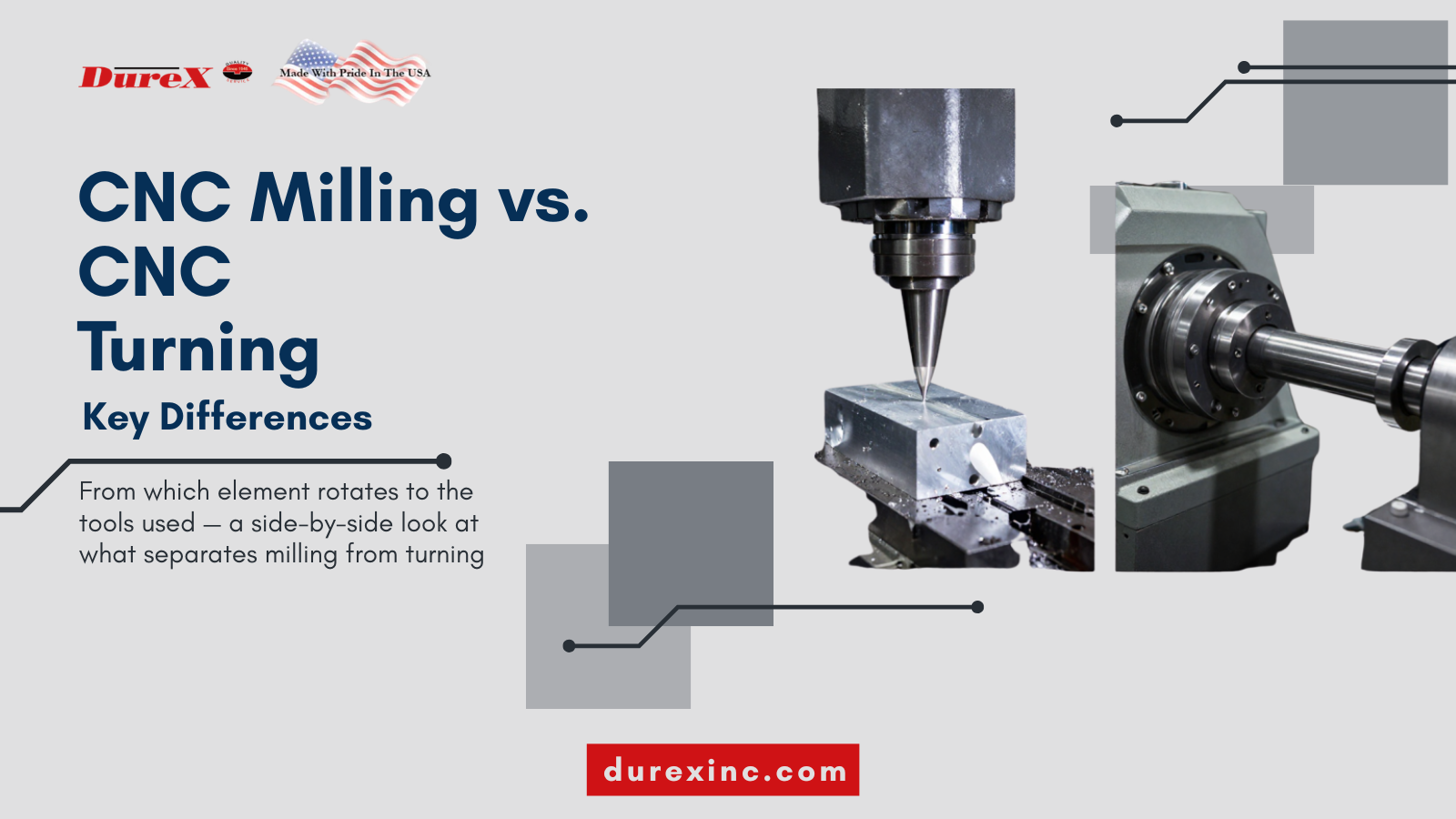
Milling and turning differ in nearly every stage of the process, from which element rotates to the tools used to remove material. The table below breaks down these differences by workholding, cutting tools, setup considerations, and the types of parts each process handles best. Reviewing it side by side makes it easier to match your part’s geometry to the right starting process. Keep in mind that these are general tendencies rather than fixed rules — some parts genuinely benefit from a mix of both.
| Factor | CNC milling | CNC turning |
| Primary rotating element | Cutting tool | Workpiece |
| Best-suited geometry | Prismatic, irregular, contoured, or multi-sided parts | Cylindrical, conical, stepped, or rotationally symmetrical parts |
| Typical features | Pockets, slots, flat faces, angled surfaces, multi-directional holes | Diameters, bores, tapers, threads, grooves, shoulders, and faces |
| Workholding | Vise, fixture, chuck, or custom fixture | Chuck, collet, faceplate, or bar feeder |
| Cutting tools | End mills, face mills, drills, reamers, thread mills, and specialty cutters | Turning inserts, boring bars, drills, grooving tools, and threading tools |
| Setup considerations | May require multiple orientations or fixtures | Often efficient for parts aligned to one central axis |
| Production advantage | Flexible for complex and varied geometries | Efficient for repeatable rotational parts |
| Common examples | Brackets, housings, manifolds, plates, molds | Shafts, bushings, pins, fittings, rollers |
Milling and turning aren’t always competing choices for a given part. A component may be turned first and then milled, or produced entirely on a mill-turn or live-tooling machine that handles both operations in one setup.
When Should You Choose CNC Milling?
Milling is the right starting point when a part’s geometry doesn’t revolve around a single central axis. It handles rectangular, prismatic, and irregular shapes far more efficiently than turning, especially when a part has features that need to be cut from multiple directions. Because the workpiece stays fixed while the tool moves, milling can produce flat surfaces, internal pockets, and angled features that a lathe simply can’t reach. The checklist below covers the part characteristics that typically point toward milling as the better process.
Choose milling when the part has:
- A primarily rectangular, prismatic, or irregular shape.
- Pockets, slots, ribs, bosses, or weight-reduction features.
- Flat surfaces that must remain square or parallel.
- Holes entering from multiple directions.
- Compound angles or complex 3D contours.
- Features that cannot be efficiently reached from one rotational axis.
- Multiple faces requiring machining in different orientations.
A good example is an aluminum electronics housing with an internal pocket, mounting holes on multiple faces, and an irregular exterior profile. None of those features could be produced efficiently on a lathe, which is exactly the kind of case where the CNC Milling vs CNC Turning decision points clearly toward milling.
When Should You Choose CNC Turning?
Turning is the better starting point whenever a part is organized around a dominant central axis rather than built from flat or angled faces. It excels at producing precise outside diameters, internal bores, and concentric features that would be difficult to hold accurately on a mill. Because the workpiece rotates continuously against the cutting tool, turning also tends to be faster and more repeatable for high-volume rotational parts. The checklist below outlines the part characteristics that typically point toward turning as the right process.
Choose turning when the part has:
- A dominant central axis.
- Multiple precise outside diameters.
- Internal bores or concentric features.
- Threads, grooves, shoulders, tapers, or radiused profiles.
- A shaft-, pin-, bushing-, or fitting-like form.
- A high production volume where cycle time and repeatability matter.
A good example is a stepped stainless-steel shaft with bearing diameters, shoulders, a center bore, and external threads. Every one of those features is concentric to the same central axis, which is exactly the kind of geometry turning is built to handle efficiently.
When is Mill-Turn or a Combined Process Better?
Some parts don’t fall cleanly into either category because they combine rotational features with non-rotational ones. A cylindrical body might need cross-drilled holes, milled flats, or a keyway — features that require a second process on top of turning. Running that part through separate milling and turning operations means additional setups, additional workholding changes, and more opportunities for datum-transfer error between machines. A mill-turn or live-tooling approach can often produce the entire part in one setup, which reduces handling and shortens overall lead time.
A combined process can reduce:
- Number of setups.
- Workholding changes.
- Datum-transfer errors.
- Inter-machine handling.
- Overall lead time.
Typical candidates for mill-turn include a cylindrical housing with cross-drilled holes, a shaft with milled flats or keyways, a fitting with turned threads and milled wrench flats, and a valve body requiring both turned bores and milled mounting features. The right call ultimately depends on the drawing, CAD model, material, tolerance scheme, quantity, and inspection requirements for that specific part.
CNC milling vs CNC turning For Cost, Speed, and Accuracy
Cost and cycle time don’t come down to which process is inherently cheaper or faster — it’s a mistake to treat either milling or turning as universally superior on price or accuracy. What actually drives cost is the combination of part geometry, material-removal volume, number of setups, and tolerance requirements. A part that looks simple on paper can still get expensive if it needs complicated fixturing or several secondary operations to finish. The variables below are what really determine the economics of a given job, regardless of which process is used.
Cost and performance are shaped by:
- Part geometry and material-removal volume.
- Number of setups.
- Tooling requirements.
- Workholding complexity.
- Tolerance and surface-finish requirements.
- Production quantity.
- Machine availability.
- Scrap and inspection risk.
- Secondary operations and finishing.
Turning is often efficient for high-volume, axisymmetric components because a single setup can complete most or all of the required features. Milling can be the more economical option when it avoids complicated fixtures or multiple secondary operations on an irregular part, even if its per-feature cycle time looks longer on paper. The least expensive process is ultimately the one that produces the required features with the fewest unnecessary operations — not necessarily the machine with the shortest individual cycle time.
DureX supports both small and larger production runs, along with prototyping, production, finishing, and assembly.
Materials and Tolerances
The material a part is machined from directly affects tool selection, cutting parameters, heat management, and overall cycle time — a factor that applies regardless of how the CNC Milling vs CNC Turning decision shakes out. Softer materials like aluminum generally machine faster and put less wear on tooling, while harder alloys require slower cutting speeds and more frequent tool changes. Material machinability also influences achievable surface finish and how tight a tolerance can realistically be held on a given feature. Understanding these tradeoffs upfront helps set realistic expectations before a part goes into production.
Commonly machined materials include:
- Aluminum
- Stainless steel
- Carbon steel
- Brass and copper
- Titanium
- Nickel alloys
- Engineering plastics
DureX’s material capabilities include aluminum, stainless steel, titanium, Inconel, Kovar, brass, copper, PEEK, and other engineering plastics.
The drawing, not the process, is what ultimately controls the required tolerance for any given feature. The drawing, not the process, is what ultimately controls the required tolerance for any given feature, typically defined using ASME Y14.5 geometric dimensioning and tolerancing (GD&T) conventions
Tighter tolerances may call for specialized inspection, temperature-controlled machining, additional finishing passes, or grinding after the initial cut. A machining quote should always distinguish general tolerances from critical dimensions and geometric tolerances rather than treating every dimension as equally tight. This distinction affects both cost and lead time, since critical features often require extra process steps to verify.
DureX publishes example machining capabilities of up to ±0.0005 inch for its listed milling and turning services, though achievable tolerance ultimately depends on the material, feature, size, geometry, and inspection method involved.
CNC Milling vs CNC Turning Decision Checklist: Which Process, or Both?

Choosing CNC Milling vs CNC Turning, or a combined process, gets easier when you work through a part’s geometry step by step rather than guessing based on overall shape. Start with the part’s dominant features and work outward — is it fundamentally round, fundamentally flat and irregular, or a mix of both? From there, factors like part size, tolerance requirements, and production volume help confirm or adjust the initial call. The framework below walks through that decision in order.
- Is the part primarily round and organized around one central axis? Start with turning.
- Does it require pockets, slots, flat faces, angled surfaces, or holes from multiple directions? Start with milling.
- Does it combine a turned body with milled or cross-drilled features? Consider mill-turn or multiple operations.
- Are the features small, slender, or difficult to support? Evaluate Swiss CNC.
- Are tolerances or surface finishes beyond standard machining requirements? Consider grinding or additional finishing.
- Are production volume, setup count, and inspection requirements driving the cost? Request a DFM review.
The table below offers a quicker reference for matching a part’s dominant requirement to a starting process.
| If your part mainly needs… | Consider… |
| Accurate external diameters, shoulders, threads, or bores | CNC turning |
| Pockets, slots, flat faces, or irregular contours | CNC milling |
| Turned geometry plus cross-holes or milled flats | Mill-turn or combined machining |
| Long, slender, miniature components | Swiss CNC |
| Very tight fit or surface-finish requirements | CNC machining plus grinding or finishing review |
What To Provide When Requesting a CNC Machining Quote
A complete quote request helps a machine shop evaluate your part accurately on the first pass, rather than going back and forth over missing details. The more specific your files and specifications are, the more accurate the resulting quote and lead-time estimate will be. Incomplete information — like a drawing without material callouts, or a model without tolerances — often forces a shop to make assumptions that don’t match what you actually need. The checklist below covers what to have ready before submitting a request.
Have the following ready:
- 3D CAD file, preferably STEP or Parasolid.
- 2D engineering drawing with dimensions and tolerances.
- Material and material grade.
- Surface-finish requirements.
- Quantity or annual volume.
- Prototype, production, or repeat-order status.
- Critical features and inspection requirements.
- Required delivery date.
- Finishing, plating, coating, heat treatment, or assembly requirements.
- Applicable certifications or traceability requirements.
How DureX Can Help Select The Right Process
Working through CNC Milling vs CNC Turning — or a combined approach — is easier with an experienced team reviewing the part alongside you rather than working from the drawing alone. DureX Inc. is an ISO 9001:2015-certified contract metal fabrication facility offering CNC milling, CNC turning, Swiss CNC, grinding, finishing, and assembly under one roof. Its Union, New Jersey facility serves manufacturers, engineers, procurement teams, and customers across the Tri-State region, supporting projects from prototyping through full production and finishing. Readers can submit a CAD file or specification directly for engineering and DFM feedback before committing to a process.