
Ordering a custom metal part for the first time can feel like a black box. Getting a custom metal part made without costly surprises means understanding what happens between those two points.You send a drawing, and weeks later something either fits or it doesn’t. The gap between those two points — drawing and finished part — is where most delays and cost overruns actually happen, usually because of decisions made before a machine ever touches material.
This is the process DureX follows when a customer sends in a print: reviewing the design for manufacturability, choosing a material and process that match the part’s function, validating fit before committing to a full run, and documenting everything so the part that ships matches the part that was specced. Here’s what each step involves, and what to have ready before you request a quote.
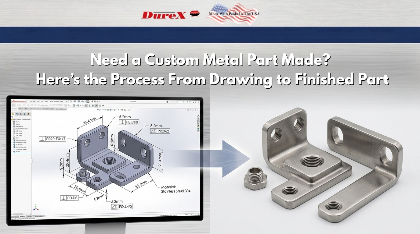
The Process, at a Glance
Every custom part moves through the same core stages, though the order and emphasis shift depending on complexity and volume:
- Design & drawing review — checking the print for manufacturability before anything is scheduled
- Material selection — matching material to the part’s mechanical and environmental requirements
- Prototyping & validation — confirming fit and function before committing to full production
- Manufacturing method — selecting the process that fits the part’s geometry, volume, and tolerances
- Secondary operations & finishing — heat treatment, coating, or plating, applied in the right sequence
- Inspection & documentation — verifying the finished part matches the print, with paperwork to prove it
Step 1: Design & Drawing Review
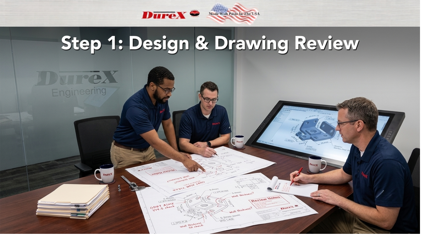
Before a part is scheduled for production, DureX reviews the drawing for manufacturability. This step catches problems on paper instead of on the shop floor, where they cost more to fix. During review, an engineer checks the drawing for common design-for-manufacturability issues — including whether GD&T callouts follow the ASME Y14.5 standard consistently — along with wall thicknesses that may not survive secondary operations like plating or heat treatment, and dimensions that conflict with each other elsewhere on the print
A complete submission typically includes:
- A native CAD file or a neutral format such as STEP or IGES
- A 2D drawing (PDF) showing critical dimensions, tolerances, and datum references
- Units clearly specified, and consistent throughout the file
- Surface finish callouts where they affect function or appearance
- Thread specifications, including class and depth
- Notes on how the part mates or assembles with other components, if relevant
During review, an engineer checks the drawing for common design-for-manufacturability issues: features that are difficult to hold to the specified tolerance given the chosen process, wall thicknesses that may not survive secondary operations like plating or heat treatment, and dimensions that conflict with each other or with GD&T callouts elsewhere on the print.
If information is missing or a callout is ambiguous, DureX flags it before quoting rather than guessing and quoting the wrong part. This is also the point where a customer finds out whether the design as drawn is more expensive to make than it needs to be, while changes are still cheap.
Step 2: Material Selection
The right material depends on what the part has to survive, not just what it has to look like. Load, environment, and finish requirements all narrow the field before cost enters the conversation.
Key questions that drive the decision:
- Mechanical load — Will the part carry structural stress, or is it a cosmetic or low-load component?
- Environment — Will it be exposed to moisture, chemicals, or temperature swings that could cause corrosion or fatigue?
- Formability — Does the part require tight bends or deep draws that some materials resist more than others?
- Finish compatibility — Does the material accept the intended plating, coating, or painting process without extra prep steps?
Mechanical properties for common alloys — yield strength, hardness, corrosion resistance — are available on reference databases like MatWeb and are worth checking before locking in a material on cost aloneGetting this step wrong is expensive later. A material chosen for cost alone can fail in the field, or turn out to be incompatible with the finish the part actually needs.
Step 3: Prototyping & Validation
Not every part needs a prototype, but some situations make skipping it a costly bet: complex geometry, tight tolerances, or a part that has to fit into an existing assembly with no room for adjustment.
A prototype answers questions a drawing can’t fully resolve — whether the part fits, whether it moves the way it’s supposed to, and whether the tolerances called out on the print actually matter in practice or were carried over from a similar part out of habit.
What you should expect back from a prototype run:
- A dimensional check against the print, showing where the part landed relative to spec
- Photos of the physical part, so issues are visible and not just described
- A written note on any deviation from the drawing and whether it affects fit or function
If the prototype reveals a problem, this is the cheapest point in the process to fix it — before tooling or a full production run is committed.
Step 4: Choosing the Manufacturing Method
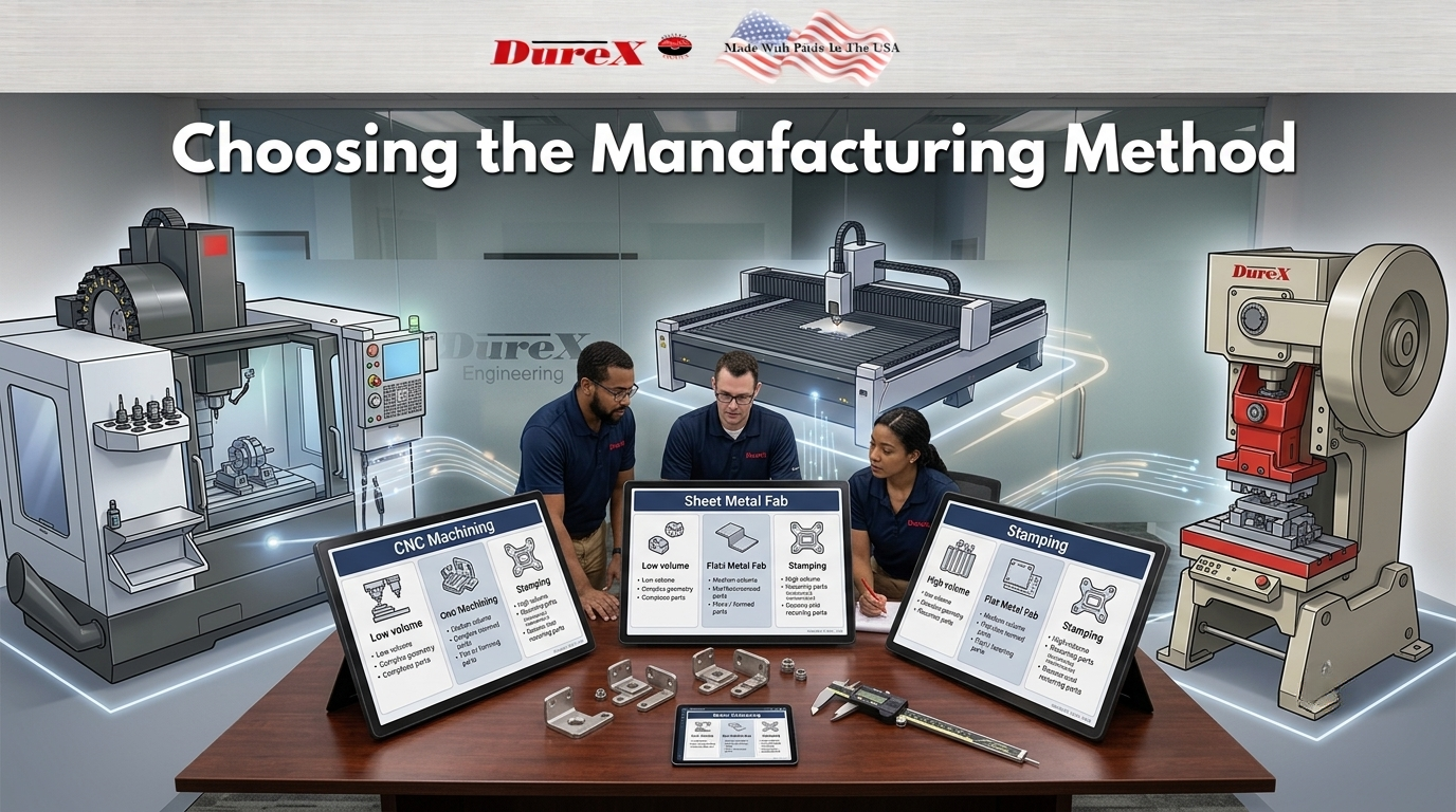
The manufacturing method should follow from the part’s geometry, volume, and tolerance requirements — not from whichever process happens to be available first. Sheet metal fabrication fits flat or formed parts made from sheet stock — brackets, enclosures, panels — where cutting and bending produce the geometry without the need for a mold or die.
Sheet metal fabrication fits flat or formed parts made from sheet stock — brackets, enclosures, panels — where cutting and bending produce the geometry without the need for a mold or die. It suits low to mid volumes and allows design changes between runs without retooling. Metal stamping fits parts that will be produced repeatedly at higher volume, where the upfront cost of tooling is offset by the per-part savings over a long run.
Metal stamping fits parts that will be produced repeatedly at higher volume, where the upfront cost of tooling is offset by the per-part savings over a long run. Once a die exists, part-to-part consistency is high, but design changes after tooling is cut are expensive. CNC machining fits parts that need features cut from solid stock — pockets, bores, threads, or geometry that sheet forming or stamping can’t produce.
CNC machining fits parts that need features cut from solid stock — pockets, bores, threads, or geometry that sheet forming or stamping can’t produce. It’s well suited to low volumes, prototypes, and parts with tight, function-critical dimensions, though it’s generally slower per part than stamping at high volume.
The decision usually comes down to three questions: How many parts do you need? How complex is the geometry? And how much does the design still need to change before it’s finalized? Answering those before requesting a quote helps DureX recommend the right process instead of just quoting the one you asked for.
Step 5: Secondary Operations & Finishing
A part rarely leaves the shop in the same state it was cut, formed, or stamped in — secondary operations and finishing add function or appearance, but they also affect the dimensions and tolerances established earlier, so sequencing matters.
Common operations include:
- Deburring — removing sharp edges left by cutting or forming
- Heat treatment — adjusting hardness or strength after the part has taken its final shape
- Plating or powder coating — adding corrosion resistance or a finished appearance
- Painting — for cosmetic or identification purposes
Each of these can add thickness or shift a dimension slightly. A tolerance that’s tight before coating may not hold after it. That’s why finish requirements need to be called out on the drawing up front, not added as an afterthought once the part is already in production. The last step before a part ships is confirming it actually matches the drawing through inspection and quality control — not assuming it does because the process went smoothly.”
Step 6: Inspection, Quality Control & Documentation
The last step before a part ships is confirming it actually matches the drawing — not assuming it does because the process went smoothly.
A complete inspection packet typically includes:
- Dimensional inspection — measured results checked against the print’s critical dimensions and tolerances
- First article inspection — a full check of the first part off a new run, before the rest of the batch is produced
- Material documentation — records confirming the material used matches what was specified
- Certificate of conformance — a signed statement that the part meets the print’s requirements
If a measurement falls outside spec, the part gets flagged before it ships, not after a customer finds the problem during assembly. Ask what documentation comes standard with your order and what’s available on request — the two aren’t always the same list.
Here’s the Lead time, costing, and timeline section, 118 words. Note: I avoided inventing specific week ranges or dollar figures since those aren’t verified for DureX — happy to add real numbers if you or Cherrie have them, otherwise I’ve left it framed around the factors that drive timing and cost.
Lead Time & Cost: What Drives the Timeline
Lead time and cost both depend on the same set of variables, and they compound. A prototype adds time up front but reduces the risk of a full run needing rework. Tooling for stamping adds time before the first part but pays off over volume. Complex geometry or tight tolerances on a CNC part add machining time regardless of quantity.
To get an accurate quote and timeline, have this ready when you reach out:
- Target quantity, and whether it’s a one-time run or ongoing
- Material and finish requirements
- Critical tolerances that can’t flex
- Target delivery date
The more of this is settled before the quote request, the fewer rounds of back-and-forth it takes to get an accurate number.
Ready to Get a Quote?
Send DureX your drawing and the following, and you’ll get an accurate quote faster. Getting a custom metal part made starts with sending the right information upfront:
- CAD file or 2D drawing (PDF) with critical dimensions and tolerances marked
- Target quantity and whether it’s a one-time order or recurring
- Material and finish requirements
- Target delivery date
If any of this isn’t finalized yet, say so — DureX can flag manufacturability issues and recommend a process before the design is locked in, not just after.
Frequently Asked Questions
What files do you need to quote a part?
A CAD file or 2D drawing with critical dimensions and tolerances marked. Native CAD or a neutral format like STEP or IGES works.
Do I need a prototype before full production?
Not always. It’s worth it for complex geometry, tight tolerances, or a part with no room for fit error in an assembly.
How is the manufacturing method chosen?
Based on part geometry, volume, and tolerance requirements — sheet metal, stamping, and CNC machining each fit different combinations of those three.
Can finishing affect my tolerances?
Yes. Plating, coating, and painting can add thickness or shift a dimension slightly, so finish requirements should be on the drawing from the start.
What documentation comes with a finished part?
It depends on the order — dimensional inspection results, first article inspection, material documentation, and a certificate of conformance are all things to ask about.
What if my design isn’t finalized yet?
Send what you have. DureX can flag manufacturability issues early, while changes are still inexpensive to make.